DC Generators
V4 AutoGen, the smartest DC charger generator to date.
Proud to present our newest model, the V4 AutoGen 48v 63amp DC Generator Charger.
Capable of charging 12v, 24v and 48v battery banks. All V4 DC Generators are equipped with our V2 AutoGen controllers,therefore giving automatic start and stop. With the use of the AutoGen mobile app, which displays battery volts, charging amps, generator running status, history graph, user programmable start timer, manual start and stop from any location around the world. Error notifications sent via email.
If you already have a generator, you can buy an automatic generator controller online here.
The V4 AutoGen constantly monitors battery bank voltage and will start automatically to bulk charge batteries. When batteries have reached 100% SOC it will shut off the generator.
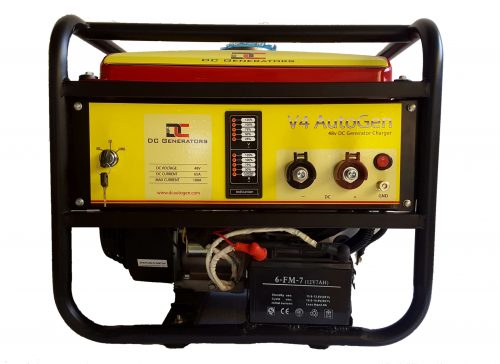
Powered by a 6.5hp petrol engine. High quality, rare earth permanent magnet alternator.
The V4-48v version has max charge rate of 63amps, V4-24v version at 125amps and the V4-12v version at 125amps.
12v and 24v models available upon request.
Tri-fuel also available upon request(petrol, lpg or natural gas).
The perfect backup system for off grid, solar, wind, telecommunications, boats, rv, caravans, etc.
Stay tuned to find out more information about our new model the V5 AutoGen DC Generator coming soon!
Below is a brief explanation of the basic construction and working of a DC Generator:
A dc generator is an electrical machine which converts mechanical energy into direct current electricity. This energy conversion is based on the principle of production of dynamically induced emf.
Construction Of A DC Machine:
Note: A DC generator can be used as a DC motor without any constructional changes and vice versa is also possible. Thus, a DC generator or a DC motor can be broadly termed as a DC machine. These basic constructional details are also valid for the construction of a DC motor. Hence, let’s call this point as construction of a DC machine instead of just ‘construction of a dc generator’.
A DC machine consists of two basic parts; stator and rotor. Basic constructional parts of a DC machine are described below.
- Yoke: The outer frame of a dc machine is called as yoke. It is made up of cast iron or steel. It not only provides mechanical strength to the whole assembly but also carries the magnetic flux produced by the field winding.
- Poles and pole shoes: Poles are joined to the yoke with the help of bolts or welding. They carry field winding and pole shoes are fastened to them. Pole shoes serve two purposes; (i) they support field coils and (ii) spread out the flux in air gap uniformly.
- Field winding: They are usually made of copper. Field coils are former wound and placed on each pole and are connected in series. They are wound in such a way that, when energized, they form alternate North and South poles.
- Armature core: Armature core is the rotor of a dc machine. It is cylindrical in shape with slots to carry armature winding. The armature is built up of thin laminated circular steel disks for reducing eddy current losses. It may be provided with air ducts for the axial air flow for cooling purposes. Armature is keyed to the shaft.
- Armature winding: It is usually a former wound copper coil which rests in armature slots. The armature conductors are insulated from each other and also from the armature core. Armature winding can be wound by one of the two methods; lap winding or wave winding. Double layer lap or wave winding’s are generally used. A double layer winding means that each armature slot will carry two different coils.
- Commutator and brushes: Physical connection to the armature winding is made through a commutator-brush arrangement. The function of a commutator, in a dc generator, is to collect the current generated in armature conductors. Whereas, in case of a dc motor, commutator helps in providing current to the armature conductors. A commutator consists of a set of copper segments which are insulated from each other. The number of segments is equal to the number of armature coils. Each segment is connected to an armature coil and the commutator is keyed to the shaft. Brushes are usually made from carbon or graphite. They rest on commutator segments and slide on the segments when the commutator rotates keeping the physical contact to collect or supply the current.
Working Principle Of A DC Generator:
According to Faraday’s laws of electromagnetic induction, whenever a conductor is placed in a varying magnetic field (OR a conductor is moved in a magnetic field), an emf (electromotive force) gets induced in the conductor. The magnitude of induced emf can be calculated from the emf equation of dc generator. If the conductor is provided with a closed path, the induced current will circulate within the path. In a DC generator, field coils produce an electromagnetic field and the armature conductors are rotated into the field. Thus, an electromagnetically induced emf is generated in the armature conductors. The direction of induced current is given by Fleming’s right hand rule.
Need of a Split ring commutator:

According to Fleming’s right hand rule, the direction of induced current changes whenever the direction of motion of the conductor changes. Let’s consider an armature rotating clockwise and a conductor at the left is moving upward. When the armature completes a half rotation, the direction of motion of that particular conductor will be reversed to downward. Hence, the direction of current in every armature conductor will be alternating. If you look at the above figure, you will know how the direction of the induced current is alternating in an armature conductor. But with a split ring commutator, connections of the armature conductors also gets reversed when the current reversal occurs. And therefore, we get unidirectional current at the terminals.
Types Of A DC Generator:
DC generators can be classified in two main categories, viz; (i) Separately excited and (ii) Self-excited.
(i) Separately excited: In this type, field coils are energized from an independent external DC source.
(ii) Self excited: In this type, field coils are energized from the current produced by the generator itself. Initial emf generation is due to residual magnetism in field poles. The generated emf causes a part of current to flow in the field coils, thus strengthening the field flux and thereby increasing emf generation. Self excited dc generators can further be divided into three types –
(a) Series wound – field winding in series with armature winding
(b) Shunt wound – field winding in parallel with armature winding
(c) Compound wound – combination of series and shunt winding
- You cannot add "V2 AutoGen - 12v DC Generator 120amp" to the cart because the product is out of stock.


